
Introduction: Telescopes, microscopes, cameras, projectors, your eyes, all have one thing in common. What is it? We will talk about how these things work using the following.
Text Reference: Haliday, Resnick, Walker 34.7
I. Ray tracing in converging and diverging lenses
II. Converging Lenses
III. Concave Mirror
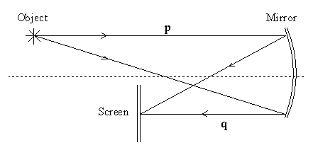
Repeat measurements, similar to those in part I, for the concave mirror.

IV. Diverging Lens
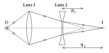
Since negative or diverging lenses do not form REAL images of REAL objects, use the thin converging lens to set up a VIRTUAL OBJECT for the diverging lens. Your setup should be as shown below. You will use this set up to determine the focal length of the diverging lens. Remember, the image created by the converging lens is the object for the diverging lens.

| (1) source position |
| (2) convex/converging lens position |
| (3) screen position without lens 2 |
| (4) concave/diverging lens position |
| (5) screen position with lens 2 |
| (6) source distance: p2 |
| (7) image distance: q2 |
| (8) f2 (from lens formula) |
| (9) f2 (from 1 / P2) |
| (10) compare (8) and (9) |
V. Convex Mirror
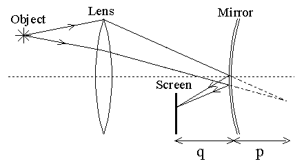
Determine the focal length of the convex mirror by using it in conjunction with the thin converging lens. First obtain a REAL image of the source using the lens alone. Interpose the mirror between the lens and the original image. Next, turn the screen around and move it between the lens and the mirror. Adjust the heights of the source, lens, and screen so the top of the screen covers the lower half of the lens and the REAL image can be seen on the screen. Move the screen and/or mirror to observe a sharp image on the screen. Record the data and calculations as before.

| (1) virtual object position |
| (2) mirror position |
| (3) final screen position |
| (4) source distance p |
| (5)image distance q |
| (6) f (from mirror formula) |
V. Simulations: You can simulate some thin lens setups here: Optics Bench Applet