
In this lab we would like to learn to build simple electrical circuits, to read electrical meters, and to verify Ohm’s law. We will try to learn about these things by measuring the resistances of some resistive materials including a lightbulb.
Text Reference: Giancoli 18.3; Haliday, Resnick, Walker 26.4, 26.5
Electrical circuits behave like an enclosed plumbing system, such as the circulatory system of the body.
There is an "electron pump", which is analogous to the heart in its function. This pump may be a battery, other power supply or generator. This power supply gives energy to the electrons in a circuit.
There is a fluid of electrons, analogous to the blood. The electrons flow through wires or conductors, analogous to the arteries and veins.
It is important to remember that the wires always have electrons in them and that the battery or generator is not a source of electrons. Rather the battery or generator simply pushes the electrons already in the wires around the circuit.
Electrical meters are devices which measure certain characteristics of this flow of electrons.
The ammeter is an instrument which measures the flow of electricity (electrons). The MKS unit of this measure is the ampere (A), which represents the flow of one coulomb per second (C/s) by a given point in the circuit. The ammeter has a very low resistance to the current in order that, when it is placed in the circuit, it does not impede the current.
The voltmeter is an instrument which, loosely speaking, measures the drop or gain in electrical "pressure" or energy between any two points in a circuit. More exactly, it measures the energy per unit charge which is dissipated (if used up by, say, a lightbulb) or generated (by the power supply) between these two points as the electricity flows between them. The unit of this measure is the volt (V), which is equivalent to a loss or gain in energy of one joule per coulomb (J/C). The voltmeter has a very high resistance to the flow of electricity in order that, when it straddles two points in a circuit, a new path for the current is not created.
As we will see, the voltmeter (measuring energy per unit charge) or ammeter (measuring current, or charge per unit time) can come in many different forms. We will look at both the digital (reads in digits) and analog (reads by an arrow being displaced proportional to the measure) type of meter.
Very important note on the multimeters which will save you time.
Ohm's Law: Without doubt, the most applied relation in current electricity is that known as Ohm's Law. This principle states that the potential difference or voltage drop V across a circuit component like a conductor is proportional to the electric current I which passes through it. The proportionality constant is called the resistance R of the conductor:
V = RI
The R has physical meaning, since it is a measure of how much the material resists current flow. The unit of resistance is appropriately called the ohm. In MKS units, R is in ohms when V is in volts and I is in amperes. Ohm's Law does not hold for all circuit elements, meaning that the "constant" R might vary for some circuit elements.
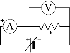
Consider the following simple circuit:

A power supply or battery supplies the applied voltage (that is the thing at the bottom). A battery supplies a fixed voltage, while a power supply generally allows the output voltage to vary. An ammeter (A) is a meter that measures the circuit current, and a voltmeter (V) measures the potential difference (voltage) across the resistance R. The straight lines are wires.
Note: Any component in the circuit which does not generate or supply a voltage to the circuit acts like a resistance. This is true for the connecting wires, the ammeter, and the voltmeter. In this circuit, however, the metallic connecting wires and the ammeter have negligibly small resistance so they do not greatly affect the current. Also, the voltmeter has a high resistance, so very little current flows through the voltmeter. Hence, to a good approximation, the ammeter reads the current through R as well as through the power supply and its variable resistance.
Thus, when applying Ohm's law to the resistance R, V and I are the voltmeter and ammeter readings, respectively.
