
Text Reference: Haliday, Resnick, Walker 27.7
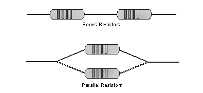
Background: Recall that resistance is proportional to the length of a resistor and inversely proportional to the cross-sectional area. Components in an electrical circuit are in series when they are connected one after the other, so that the same current flows through both of them. Components are in parallel when they are in alternate branches of a circuit. Series and parallel circuits function differently. You may have noticed the differences in electrical circuits you use. When using some decorative holiday light circuits, if one lamp burns out, the whole string of lamps goes off. These lamps are in series. When a light bulb burns out in your house, the other lights stay on. Household wiring is normally in parallel. It helps to think of the water analogy - if these resistors are turbines or pipes which slow the flow of the water, what happens if you add two in series or in parallel, does it allow the water to flow more freely or less? What happens when one breaks (and water will not flow through it)?

You can monitor these circuits using a Current and Voltage meters and see how they operate. One goal of this experiment is to study circuits made up of two resistors in series or parallel. You can then use Ohmís law to determine the equivalent resistance of the two resistors (if the two were replaced with one that has the same effect as the two).
| Multimeter | two 47-W resistors |
| Alligator clip wires | two 100-W resistors |
| AA Battery holders and batteries | two 200-W resistors |
If you do not have a resistor of the exact value shown, use the closest value that you have.
1. For two resistors in parallel, try to determine the relationship between the current supplied by the power supply and the current through each resistor for a fixed voltage.
2. For two resistors in series, try to determine the relationship between the current supplied by the power supply and the current through each resistor for a fixed voltage.
3. For two resistors in parallel, try to determine the relationship between the voltage supplied by the power supply and the voltage across each resistor for a fixed voltage.
4. For two resistors in series, try to determine the relationship between the voltage supplied by the power supply and the voltage across each resistor for a fixed voltage.
Hint: consider trying more than one combination of two resistors (e.g. try two resistors the same as each other then two that are different from each other).
1. From your measurements, use Ohm's Law to determine the equivalent resistance (Req) - this is the effective resistance as if the whole circuit was one resistor - of the circuit for each of the circuits you tested.
2. Study the equivalent resistance readings for the series circuits. Can you come up with a rule relating the equivalent resistance (Req) to the individual resistors in a series circuit with two resistors? Can you do the same for a parallel circuit?