DC Circuits (116 review)
Purpose:
To familiarize yourselves with the basic tools: breadboards, power supplies, DMM
(digital multimeters) and resistor circuits (including voltage dividers). Measuring
and calculating R, V, I. Sketching circuits.
Reading: read your general physics (116) text
chapter on Direct Current (DC) circuits
Equipment:
- Breadboard and Jumper Wires -
watch
this video on how to use breadboard, and common errors!
- DC power supply
- DMM (2)
Note: Use either the small orange ones, the BK Precision
2860A, or the higher precision rack mount DMMs. For measuring voltage, the
small orange DMMs are as good as anything, but for measuring small currents,
you probably want to use one of the other DMMs.
- Assorted fixed Resistors (nominal 68W, 100W,
220W, 1kW)
[note these are units of Ohms. If you print this, they
might turn to W's, so be careful not to confuse with Watts!]
- 5k Potentiometer
Procedure:
Preliminary: Measure the resistances of the four fixed resistors
with the DMM. Read the tolerances from the resistors. Are they within the
specified tolerances?
Notes on using the DMM to measure current:
- For
the 2860A measuring DC or AC currents, one wire is in COM, and the other in
one of the current inputs. The 20A input is only for currents larger than 200 mA; the
range 200mA/20A is for any current over 200mA. For currents
below 200mA, use the other input (uAmA) and vary the range as needed (DC
currents use the light blue ranges). Range – 200uA reads in micro-Amps
(resolution 0.1uA, thus the smallest current that can be read is 0.1uA);
Range- 2 mA, 20 mA, or 200 mA (“200mA/20A”) reads in mA;
Range – 20A, with lead in the 20A input, reads in Amps.
- THE IMPORTANT THING IS TO NEVER TRY TO MEASURE CURRENT IN PARALLEL like
you measure voltage – that WILL blow a fuse in the meter.
- BE SURE you know how to measure current before you try with any DMM.
In order to check if the fuse is blown, you can easily check the
continuity betwen the current (uAmA) input and COM inputs with the
diode/contonuity function of a second DMM (ask how to do this if you do not
understand.)
A. Resistors in Series
- Calculate the series resistance for the three larger resistors. (Note:
when asked to calculate a value, you are typically trying to predict what you
will measure, so where possible, you should calculate using previously
measured values - unless all you have for your calculations are theoretical
values.)
- Using the DMM, measure the net resistance of the three resistors in series. Note
that the power supply should never be connected when using the DMM to measure
resistance. Does it match the
calculated value within tolerances?
- Draw a circuit (using a circuit simulation program) with a DC voltage supply connected to three resistors in series.
- Calculate the current and the power dissipated in each resistor if the series
combination is hooked up to a 5V power supply. Compare the power to the resistors'
power rating (0.5W).
- Set the DC power supply to 5V, and connect it to the three resistors in series. Measure the voltage of the power supply with the DMM.
- Be certain you understand how to measure the current correctly
before you try incorrectly and damage a meter! Measure the current supplied
by the power supply with the DMM. Does it match the predicted value?
- Draw the circuit with the DMM attached to measure the voltage drop across the middle
resistor of the three resistors. Remember that "draw" always means to use a
circuit simulation program.
- Calculate and measure the voltage across each individual resistor. Do the three
add up to what they should?
B. Voltage Dividers
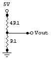
- Suppose you have a fixed voltage supply that puts out only 5V, yet you need a 1V source:
how can you reduce 5V to 1V? The easiest way is to use a voltage divider. This
is just two resistors in series chosen so that the voltage drop across one of them is 1V.
If the total voltage drop is 5V, then one resistor needs to be four times as large
as the other. Choose the best combination from the four fixed ones you have and
calculate and measure the output voltage.

- Use a variable resistor (potentiometer) in place of the two resistors and
adjust it so that you can get a 1V output. Measure the
three resistances of the
potentiometer (all three combinations of two wires coming
out of it), and confirm that they work out to have the expected relationship.

C. Resistors in Parallel
- 1-5. Connect the same three resistors from the first (series) section in parallel;
repeat steps A.1-5 for the parallel combination of resistors.
- 6-7. Repeat steps A.6-7 for the parallel combination measuring currents instead of
voltages.
D. Complex Circuits with Resistors
- Connect the 68W resistor in series with the parallel
combination from part C. Calculate, measure and compare the equivalent resistance of
the composite circuit.
- Attach a 5V power supply and measure and calculate the voltage
and current across the 68W resistor. Does
it make sense?
E. Reason (calculate) and then check the following with a
circuit simulation program. Be sure to show the output from your simulation in your discussion.
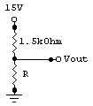
- Cosider the voltage divider

If you want Vout to be 6V, what is the required value of R?
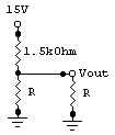
- A voltage divider has the downfall that it wastes a lot of power. If the output
voltage is dissipated through a resistor of value R (the "load"), what
percentage of power is being supplied to the load? Use the value of R
from the last problem.

DO NOT FORGET TO GO ON TO PART 2, AC CIRCUITS


