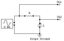
We would like to find the -3 dB point of the DMM (recall that is where the signal is attenuated by 0.707 of the original.) Set the DMM to the 2 V AC setting. Read the output of the function generator with the DMM. Turn on the function generator, and set it to output a sine wave. Set it at 1 V (as read by the DMM) and 100 Hz. Leaving the function generator's amplitude alone, measure the voltage according to the DMM at 100, 200, 500, 1k , 2k, 5k, 10k, 20k, and 50 kHz. Take two additional readings at frequencies in the interval around where the meter crosses its -3 dB point. Plot the DMM reading versus frequency and also plot the attenuation (readings in dB) vs, frequency.
Recall: a low pass filter could be used, for example, to eliminate interference on sensitive electronic components from the high frequency signals of nearby radio stations.
The "3dB point" is the frequency at which the amplitude of the output signal is down to 70% of the input voltage. The 3dB point occurs at:
![]()
The 3dB point is typically quoted as the cutoff for an electronic filter (low-pass or high-pass). Theoretically, the phase difference between the input and output signal is given by:
![]()
Setup a low pass filter with a cut-off frequency of approximately 1 kHz using the resistors and capacitors from lab. The oscilloscope should be attached to read the input voltage on channel 1, and the output from the filter on channel 2. Set the function generator to output approximately 1 Vp-p. Vary the input frequency up and down, confirming that the filter works as it should. Then plot the attenuation and phase as a function of frequency, for the same frequencies as in part B.

Switching the place of R and C in the last experiment, verify that it works as a high-pass filter and verify the cut-off frequency.
Using the same low pass circuit, with the function generator set to 20 kHz, look at the output of a square wave input. Make a sketch of the input and output. Do the same for a triangular wave input.
Using only CircuitMaker, repeat step E (except instead of the triangular wave input, try a sine wave input) for the high pass circuit with the function generator set to 100 Hz. Print the input and output from CircuitMaker.