OpAmp (741 or similar, general purpose)
IC extraction tool
R = 10k
visible light NPN phototransistor
OpAmp LM386
Microphone
Speaker
C = 1nF, 47 nF, 0.1 uF, 1uF, 10 uF, 100uF
555 timer IC
In last week's lab, we used operational amplifiers to amplify voltages. In this lab we will experiment with various other operational amplifier circuits.
Suggested Reading: Horowitz and Hill pp. 284-290 (oscillators and timers)
NOTE: check uic in transient analysis checkbox in order to use the 555 in CircuitMaker
A. Optical Detector
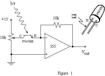
1. Construct the optical detector circuit shown in figure 1 using a 741 amplifier (instead of the 355) and an NPN visible light phototransistor. The PN168 shown in the diagram is obsolete, and we currently have some of these, and also the SFH310. Vary the collector voltage VC to determine whether the phototransistor acts more like a current source controlled by the incident light or variable resistor whose resistance changes with light.

2. Observe and print out or take a picture of the output waveform, being sure to note where 0 V DC is. Confirm that the output is caused by light incident upon the phototransistor. What is the source of the time varying light incident on your detector? (Hint: Measure its frequency.) Test your hypothesis by disabling the offending light source. Is there still a residual light level (show the output again)? What is its source?
B. Differential/Comparator
1. Set up the differential amplifier below. Design it for a gain of 2, using resistors in the kohm range. Using positive DC voltages for each input, measure the input and output for a few different voltages, keeping Vin+ > Vin-. Does the circuit behave as expected? What if Vin+ < Vin-?
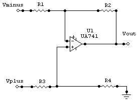
2. Turn your differential amp into a comparator as described in class. Try to set the two inputs equal to each other and describe what happens.
C. Simple Audio Amplifier
Use a 386 audio amplifier to make this g = 20 circuit:
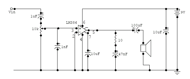
Try and
connect a capacitor between pins 1 and 8 (pin 1 is for the positive side of the
capacitor); the capacitance should be some value between 0.1 microfarads and 15
microfarads. Find one that works
best. Remember that you can adjust
the volume with the pot to avoid nasty shrieks to come out from the speaker.
D. The 555 Timer IC
Hook up the classic oscillator configuration (from class, or from H&H pg. 287) for the 555 chip. The capacitor (use 0.1uF) charges through resistors RA and RB (use 10k each). When the capacitor voltage reaches 2/3 Vcc (monitored by pin 6; use 15 V for Vcc here), the 555 changes its internal state and internally connects pin 7 to ground. Once the capacitor has discharged to 1/3 Vcc (detected by pin 2), the capacitor begins charging again and the whole cycle keeps repeating itself. (Pins 2 and 6 are therefore connected directly to the cap. Both have a very high input impedance.) The output at pin 3 is internally connected to Vcc when the capacitor is charging, and set equal to ground (approximately) when the capacitor is discharging. The result is a periodic pulse waveform at the output.
![]()
E. Clock
Design a clock in Circuit Maker which pulses once every second. The pulse should be very short compared to a second. Since the 555 above has a duty cycle>50% (the duty cycle is the percent of time that the output is high; in the standard configuration, the output is HIGH more of the time than it is LOW), it is okay to make a clock whose output is generally high, but pulses low. Be sure to show the circuit and the output.
Other types of oscillators: NO NEED TO DO THESE (F-I), but you might want to try the toy organ
F. Sawtooth Wave
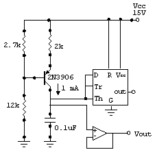
You can generate a sawtooth wave oscillator by replacing RA and RB with a constant current source (a transistor). Notice you do not want to take the output from the timer chip, but directly from the capacitor. Choose a standard op-amp for a buffer: what purpose does the op-amp buffer serve? What do you expect the output from the buffer and the output from the timer chip to look like?
G. Triangle Wave
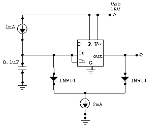
In the sawtooth wave circuit, the discharge was fast. If we can design a circuit to discharge at the same rate as charging, then we can make a triangle wave. This could be done, for instance, by making a reversible constant current supply (which is really just a transistor circuit as in the previous circuit) that charges the capacitor with 1 mA and then discharges the capacitor with 1 mA of current away. This is put into practice above. Can you describe how this circuit works? Please hook this circuit up in Circuit Maker (use constant current sources as shown) - not in lab - and observe the voltage on the capacitor. Is it as predicted?
H. Sine Wave
Sine waves are the most difficult to create. A standard circuit used to create them is the Wien Bridge Oscillator (see H&H 5.17). Instead of all these different circuits, we can use one IC known as a VCO - Voltage Controlled Oscillator (e.g. the 566).
I. Toy Organ
The following circuit depicts a 555 multivibrator. Build the circuit as shown and monitor the speaker input. The potentiometer can be adjusted to change the frequency. The switches allow additional capacitance to be switched in and out which changes the frequency. If you think it is too loud simply adjust the 10k potentiometer on the output (volume control).
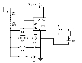
C1, C2, etc. should be between 0.01 and 0.1 uF approximately, or just make them all 0.1uF, and get combinations by pushing more than one button at once. C4 should be 4.7uF. Be sure to observe the polarity of the capacitors. The frequency is also adjustable via the potentiometer R1. Try it out.
 this is an image of
the grey buttons, top view, with wiring to the 4 pins shown.
The End