Properties of the Electron
The electron is pretty darned important. If it wasn't for
the electron, we wouldn't have ice cream in the summer. It is pretty
small. It has a charge. It behaves like a particle sometimes, and
then at other times it behaves like a wave. I guess that holds for all of
the fundamental particles, but the electron was the first fundamental particle
to be discovered.
In the following series of experiments, we will not only study
the property of electrons, but we will learn about a number of ground-breaking
(Nobel Prize-winning) experiments which changed the way we understand matter.
Safety: you will be using very delicate equipment and very high
voltages. Before you turn on any power supply, be sure that you and your
partner check the circuits until you are certain you have it right. Then,
do not try to move any wires without turning off all of the power
supplies. Treat the Cathode Ray Tubes with extreme care, they are fragile,
and we do not have extras.
References: any introductory text for the properties of an
electron in magnetic and electric fields, and any modern physics text for Bragg
scattering.
Background: your introduction should stress the importance of
these experiments and the breakthroughs they allowed.
Experiment 1 - The effect of E and B: measuring the
charge and the mass of the electron
In a series of experiments performed just prior to the turn of the century,
J. J. Thomson was able to show that electrons behaved as particles of mass m
that carried a fixed amount of (negative) electrical charge e. These
particles moved in trajectories governed by the laws of electricity, magnetism
and classical mechanics. Thomson received the Nobel Prize for this work in
1906. (J. J. Thomson's son, G. P. Thomson, received the Nobel Prize in 1937
for experiments that showed that electrons could exhibit wave-like properties
as well.) Thomson was not able to measure the charge or mass separately but
only the ratio of these two quantities, e/m.
A. Basic E&M theory
In order to do all of the exercises in Experiment 1, you
will need to use the basic equations relating potentials to electric fields, and
EM fields to forces on charges:

In addition, because of the way
the apparatus is setup, we will approximate that the electric and magnetic
fields that we produce are constant over the area of interest.
B. Experimental Apparatus

- Deflection Tube (pictured below)
- 5000V variable power supply (e.g. Tel-Atomic kV 813 Power Supply)
- Standard DC Power Supply
- Multimeter
In this exercise you will repeat some of Thomson's experiments using
apparatus similar to his. This apparatus consists of an evacuated clear glass
bulb containing an electron "gun" similar to that found in a modern
TV picture tube. This gun is a heated filament that emits electrons that are
then accelerated toward a metal plate kept at a positive potential relative to
the filament. A narrow slit in the plate allows the electrons to pass through,
and they eventually strike a flat mica sheet on which there is printed a
centimeter scale. Metal electrodes above and below this mica sheet allow us
also to apply electric fields to the region.
Apparatus for Measurement of e/m for electron
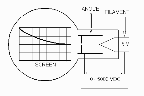
The glass bulb is supported between two large coils of wire. The
arrangement of these two coils (suggested by Helmholtz) is such that the
separation between them is equal to one-half of their average diameter. A
current through these coils will create a magnetic field B which is
substantially uniform over the central region between the coils.
You need two power supplies: You can use the high-voltage power
supply for both the accelerating potential (anode potential, Va)
and the deflecting potential (Vd). If you have access to two
separate high-voltage supplies, then use two separate ones for those two
voltages. Any regular low-voltage DC power
supply can be used for the Helmholtz Coils.
- Notice that each Helmholtz coil has a terminal labeled A and one labeled
Z. Connect the Z terminals to one another and the A terminals to the DC
power supply. You will want to include the multimeter in the circuit
to give you a better value for the current through the coils.
Important note: never exceed 1A of current in the Helmholtz coils for an
extended period of time (not more than a few minutes).
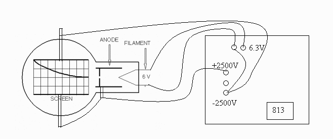
- The filament in the electron gun should be connected to the two 6.3V
terminals on the TEL-Atomic power supply, or to a low-voltage DC power
supply set at 6.3 volts. The plus and minus terminals on
the variable part of the power supply should be attached across the filament
and anode, to supply the accelerating voltage from the filament toward the
anode. In addition, the same voltage (or the second high voltage power
supply) should be attached across the
parallel deflection plates. Make sure that appropriate banana plug
connections are used so that no end of a plug is left exposed. The
connections described are pictured below with a single power supply powering
both the deflection and accelerating voltages.
- Notice that if we want to observe the deflection due to
only the
magnetic field, we don't want any potential difference across the parallel
plates. In that case you would want to detach the deflection plates
(the terminals coming from the top and bottom of the large part of the bulb) from the + and -
connections on the power supply, and simply short the two plates
together. You will want to do this at various times in the lab
as noted in the procedure.
C. Calibration of E and B:
Exercise 1.1: Determine theoretically for this apparatus the magnitude of E as a function of voltage
applied: considering these are parallel plates
(thus a constant field),
and each square between them is 1 cm, what should the
theoretical relationship be for E vs. V for this apparatus? Give
the answer only in terms of V and numerical quantities.
The magnitude of magnetic field, B, from the coils is given by
the manufacturer as
(1.2)
 ,
where
N = number of turns of wire in each coil (320)
r = mean radius of coils (0.068m)
I = current in Amperes
D. The Effects of Electric and Magnetic
Fields on a Charge
- Once you are certain the circuit is hooked up correctly, turn on the
high-voltage power supply and slide the 5kV voltage control up. When the
voltage exceeds about 1500 Volts, you will begin to see the blue glow of the
electron beam (did you know electrons were blue? Why are they blue?). (The electron beam is easier to see in a darkened
room.) If you are using a single high-voltage power supply for both the
acceleration and deflection, you will notice that as you increase the accelerating voltage,
you are also increasing the deflection voltage, hence the deflection does
not vary! (At some point try to get your hands on a second power supply
and vary them separately, and you will see you can vary the deflection.
Exercise 1.2: You observed this above, now show theoretically that the deflection does not vary if the
accelerating voltage and deflection voltage are changed at the same
rate. (Hint: You need to show that the y-position of
the beam as a function of x is independent of the accelerating/deflection
potential. You might do this by finding the horizontal velocity of the electron being
accelerated by the potential V using energy conservation, and then finding the
resulting displacement in the horizontal direction after a
certain deflection in the
vertical direction due to the electric force.)
Exercise 1.3: From your derivation from Exercise 1.2,
and by measuring the actual experimental deflection, show that
the equation you derived from
exercise 1.1 is true (or not).
That is, find the correct, experimental calibration relating E and V (still
assume that E is constant).
Exercise 1.4: What is the theoretical shape of the path of the
electrons passing between the parallel plates? Plot the theoretical trajectory
(use the equation you derived) using 3000 V (using Matlab, Excel or anything else). Does it look like what you actually
see (take a picture of the actual)?
- Turn off the power supplies and disconnect the parallel plates
from the voltage source as described in Section B.3. Turn it back on
to see the horizontal electron beam.
- Now turn on the Tesla Coil power supply and observe the effect of the magnetic
field on the moving electrons. Vary the accelerating voltage as well as the
magnetic field. Observe the effect of reversing the direction of the
magnetic field by reversing the direction of the current through the Helmholtz coils.
- Check your knowledge of the direction of the magnetic field and the
direction of the force it exerts on a moving negatively charged particle.
Exercise 1.5: What is the direction of the magnetic field between the Helmholtz coils for
a given direction (CW or CCW) of the current? What is the direction of the force that
this field exerts on a moving electron?
Exercise 1.6: Recall that a charged particle moving in only a
magnetic field moves in a circle. Using Newton's second law for uniform
circular motion, and a determination of the speed due to the accelerating
potential (Exercise 1.2), show the following result:
(1.3)
The voltage V is read directly from the high voltage power
supply. For a given current, the magnetic field B may be computed from
Equation 1.2, above. All we need is a value for R in order to be able to compute
the ratio of electronic charge to electronic mass. The electron beam
begins at the origin. The grid allows you to follow its coordinates as
it travels. A little geometrical analysis will show that, for circles
passing through the origin and the point (x,y), the radius R of that circle is given by
(1.4)

If you are not comfortable with it, you should derive it.
E. Measuring e/m
We would like to measure e/m. Do it in a way similar to the
following:
- For a given high voltage V, adjust the coil current I so that the electron
beam passes through the point: x = 10, y = + 2.6.
- Keeping this same voltage, reverse the magnetic field and alter its
strength until the beam passes through the point: x = 10, y = - 2.6.
- Use the average value of these two currents when computing the magnetic
field in Equation 1.2.
- Repeat this process for five different values of the accelerating voltage
and compute five different values for e/m. Average the
values and find the 90 % confidence interval for the five values.
- Compare your final value to the accepted value within confidence limits.
F. Crossed Electric and Magnetic Fields
- Reconnect the parallel plates to deflect the electrons with both an
electric and magnetic field.
- A combination of electric and magnetic fields applied at right angles
forms what is known as a velocity selector and is a common occurrence in
mass spectrometers and particle accelerators. The physical principle is
quite simple: an electric field E exerts a force qE on a charged particle
while a magnetic field exerts a force qvB on the same particle. When these
two forces are equal in magnitude but oppositely directed, the particle will
move in a straight line. Its velocity will be given by v = E/B (set qE=qvB!).
- You can approximate this condition over a narrow portion of the electron
beam. Adjust the potential difference applied to the electrodes above and
below the beam and the magnetic field until you see the beam move in a
straight line across the middle portion of the tube (where the magnetic
field is most nearly uniform). Use the approximate value of speed
which you had calculated earlier from energy conservation (using
your
value of e/m) to get an approximate value of E you are using in the velocity
selector. Does this value of E match what you had calibrated in
Exercise 1.3?
Experiment 2: Diffraction of Electrons
The purpose of this experiment is to demonstrate that electrons have
wave properties. Specifically, we wish to show
- that electrons can produce diffraction effects when scattered from a
Carbon target,
- that the pattern so produced follows the same Bragg equation that
applies to xradiation, and
- that the results confirm the de Broglie hypothesis - namely, that all
material particles have a wavelength which is inversely related to momentum.
A. Theory:
The de Broglie wavelength of a material particle is
(2.1)

where h is Planck's constant. For electrons accelerated through a
potential difference V, the velocity v can be obtained from the classical expression
(2.2)

and substituted into the de Broglie relation obtaining:
(2.3)

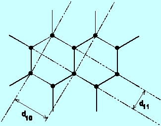
If a wave is diffracted off of Bragg planes, it will bounce off the Bragg
planes randomly in all directions, creating a fundamental diffraction ring
at an angle theta from the original path, given
by the relationship governing constructive interference
(derived in Physics 251).
(2.4)

where d = the interatomic spacings, D is the ring diameter, and L is
the pathlength from the carbon target at the gun aperture to the luminescent screen.
Combining this with the previous relation,
(2.5)

If you vary V, then D varies
(everything else is constant) so the relation can be verified by
means of a graph related to these variables.
B. Apparatus:
The electron diffraction tube, TEL.555, comprises a 'gun' which emits a
narrow converging beam of electrons within an evacuated clear glass bulb on the surface of
which is deposited a luminescent screen. Across the exit aperature of the 'gun' lies a
micromesh nickel grid onto which has been vaporized a thin layer of graphitized carbon.
The beam penetrates through this carbon target to become diffracted into two rings.
Note that now your electrons are green, while earlier they were blue - why do
you think this is?
Connect the tube as shown in the following diagram:
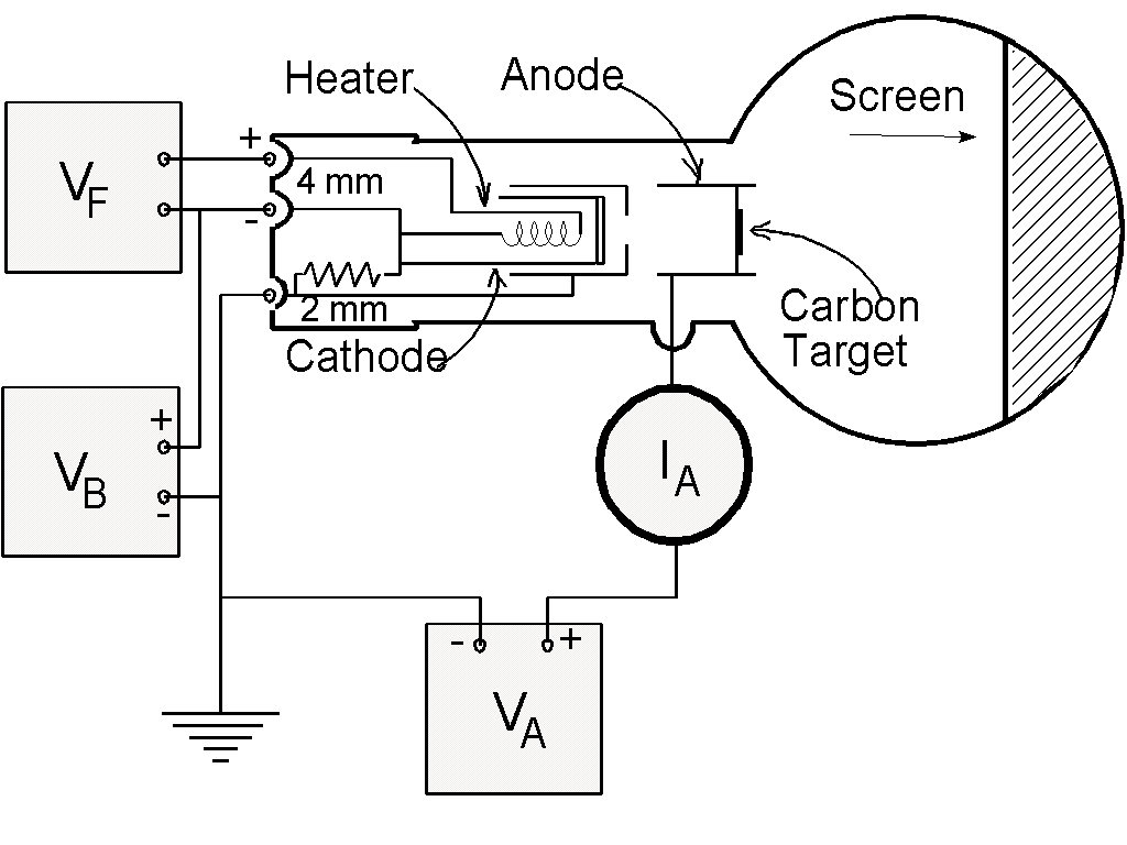
-
Click here for a "real" diagram
rather than a block diagram.
-
Filament Voltage ( VF ). . . 6.3 V ac (on the 813 Power
Supply)
-
Anode Voltage ( VA ). . . 2500 - 5000 V dc (on the 813
Power Supply)
-
External Bias ( VB ). . . 0 - 50 V dc (on the 801 Power
Supply)
-
Anode Current ( IA ). . . 0.15 mA at 4000 V ( 0.20 mA
max.)
-
Note: VA and VF are on
the same, 813, power supply. Use the ground on the 813 for the
common ground for all the supplies.
-
If you are using the diffraction tube with the "Universal Stand":
Connect C5 on the universal stand to the negative on the HV supply. F4
goes to the positive on the heater supply and the low voltage bias. G7
goes to the positive lead on the HV supply. F3 goes to the negative on the
heater supply.
C. Experiment:
- Measure the pathlength from the Carbon target at the 'gun' exit aperture
to the luminescent screen as accurately as possible.
- Switch on the heater supply and wait one minute for the cathode
temperature to stabilize.
- While watching the meter which reads the anode current, gradually begin
to increase the anode voltage. The anode current should never be allowed to exceed 0.2 mA.
Higher anode voltages can be achieved without exceeding the limit by increasing the
external bias control which also helps in focusing the electron beam. Set the voltage to
2500 volts for now.
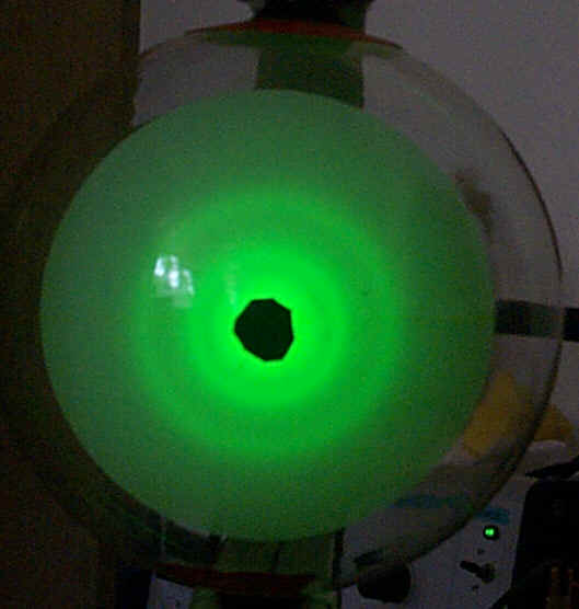
- Two prominant rings about the central spot are observed. Variation in
the anode voltage causes a change in diameter.
- Measure and tabulate the ring diameter, D, for both the inner and the
outer rings at different anode voltages, say from 2500 volts up to 5000 volts in steps of
500 volts.
- Plot a graph of V-½
versus D for each ring. From the slopes together with equation (5) determine the value of
the two spacings d in Carbon which would yield these results.
- Optional: look up the spacings in carbon to see if these are correct
(hint, they are 0.12 nm and 0.21 nm).
- In your conclusions, be sure to say a little bit about how your results
address the stated objectives.


 ,
where


