PRECESSION
of a GYROSCOPE:
L,
I, a, t
PURPOSE: measure the precession rate of a gyroscope and compare the measured value to theoretical expectations.
THEORY: A gyroscope is a rigid system of particles symmetrical about an axis and rotating about that axis. The symmetry about the axis guarantees that any component of the angular momentum Lk of particle k that is perpendicular to the axis will be compensated by an equal and opposite component due to the diametrically opposite particle. Thus the angular momentum L for the entire rigid body points along the axis of rotation. The angular momentum dL of a particle of mass dm located a distance r from this axis is just
dL = r
x dp = dm(r x v)
If v is perpendicular to r, as in the case here, then v = wr and
dL = dm r2 w
If one integrates dL and dm over an entire rigid disc of radius R and mass M one obtains
L = MR2w/2= I w (1)
where I = MR2/2 is the moment of inertia of the disc.
In analogy to Newton’s First and Second Laws, L
remains constant unless acted on by an external torque t:
dL/dt = t (2)
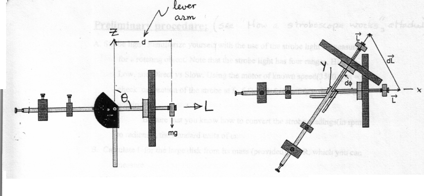
Assume a gyroscope is balanced in the
horizontal position, q = 90° in the
Figure 1.1
below. In the Figure, the z axis is vertical and
the angle f gives the direction of L
in the xy plane.
 side
view top view
Figure
1.1: Torque Applied to Horizontal Gyroscope
Suppose now that a small mass m is attached to the end of the gyroscope shaft at a
distance d from the point of support., If the gyroscope axis is horizontal, q = 90o and this resultant torque t = r x F has magnitude mgd; its direction is perpendicular to L and in the xy plane As a result, t changes the direction of L but not its magnitude, causing L to rotate about the z axis. The rate of rotation (precession) of L is easily computed, as follows.
For small changes in the direction of L,
L df /dt = t = mgd (4)
Thus the rate of precession, W = df / dt, is thus given by
W = mgd
/ L = mgd / Iw
If the angle q between L and the
vertical is not 90o, the torque will be mgdsinq
instead of mgd, with corresponding effects on W.
 Preliminary procedure:
(See "How a Stroboscope Works", attached)
A. Strobe light. Familiarize yourself with the use
of the strobe light to measure w for a rotating object.
Note that the strobe light has four ranges: High vs Low, and Direct vs Slow.
Using the motor of known speed (3500 rpm = f1)
check calibration of the strobe at f1, f1/2, f1/3,
f1/4, and f1/5. It should be within 5%.
Be sure that you know how to convert the strobe readings (in rpm)
to radians/s, the standard units of w.
B. Calculate I for the large disk from its mass (provided) and R, which you can measure.
C. Measure the distance d between the small added mass and the center of the gyroscope.
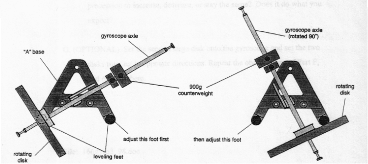
D. Level the gyroscope on the table as follows.
(1) Purposely make the apparatus unbalanced by moving the 900g counterweight towards the center.
(2) Adjust the leveling foot on one of the legs of the base until the gyroscope disk is aligned over the leveling foot on the other leg of the base. See Figure 2.
(3) Rotate the gyroscope 90 degrees so the gyroscope axle is parallel to one side of the "A" and adjust the other leveling foot until the shaft will stay in this position. See Figure 2.
(4) Adjust the position of the 900g counterweight until the gyroscope is balanced without the add-on mass. The 30g counterweight can be used to fine tune the balance.
Experiments:
E. Using the string, start the balanced gyroscope rotating such that q = 90o. Measure w with a strobe light. Add a small weight to start the precession of the gyroscope. Measure the rate of precession with the aid of a stopwatch. Remeasure w, which will have changed slightly due to friction. Compute the expected value of the precession rate W and compare to your observations. Repeat several times. Explain why the rotation is in the observed direction, i.e. clockwise or counterclockwise, looking from the top down.
F. Repeat the experiments of part E but with q = 45o.Do you expect the rate of precession to increase, decrease, or stay the same? Does it do what you expect?
G. (OPTIONAL). Set the second large disk onto the gyroscope and set the two disks rotating in opposite directions. Repeat the observations of Part F, and explain them.
How a
stroboscope works
Stroboscopic effects are produced when an intense light pulse is repeated at precise time intervals. If light flashes at frequency fare directed upon a rotating or vibrating object oscillating at frequency f1, the object will appear stationary if f = f1. This apparent cessation of motion, called the "stroboscope effect", occurs because the object is illuminated at precisely the same phase of each cycle. This apparent cessation of motion will also occur when the light frequency is a submultiple (one half, one-third, one-quarter....) of the movement frequency.
1 .Play around with the stroboscope. Observe what happens with a known, steady rotation such as a motor shaft turning at 3500 rpm (58 Hz). Start with the stroboscope at its maximum frequency fmax about 65 Hz. Observe the images of the motor shaft as f is gradually decreased.
2. How to measure an unknown frequency f if f1 <fmax. Set the stroboscope to fmax then slowly decrease f until the motion "freezes". The highest f which "freezes" the motion is f1.
3. Measuring an unknown frequency f if you’re not sure f1<fmax. You have to proceed more carefully, because the highest available frequency which freezes the motion may be a submultiple of f1 = f1/n, where n is unknown.
A. Start at the top, measure the highest possible freeze frequency. Call it fn.
B. Slowly decrease f until the motion again freezes. Call the resultant frequency fn+1.
C. Calculate f1 from the relation,
![]()
This relation can be derived by noting that
fn = f1 / n,
fn+1 = f1 / (n+1)
and solving the two equations for f1.
The Electronic Brazing Company strobe light has 4 ranges. A switch on the back can be set to "direct" or "slow" mode, providing a 100 X or 10 X multiplier for the dial reading. The knob on the side turns the strobe on but also permits setting the strobe to High or Low dial range. The resultant ranges(in rpm) are:
Low High
Slow(xl0) 60- 370 300- 1500
Direct (x100) 600 - 3700 3000 - 15000
File /coursework/l66strobe3_98.doc